

Kuika’s Process Automation module streamlines mobile and web application development by automating workflows, enabling efficient management of repetitive and time-sensitive tasks. This results in significant savings in time and effort. With Process Automation, workflows can be designed, system and custom actions can be added, and task assignments can be managed. This module is a built-in feature of the Kuika platform and does not function as a separate tool. All integration operations, system actions, and data management capabilities available in Kuika can be directly utilized within Process Automation.
The Process Automation module can be applied in various areas such as automated reporting, data analytics, HR automation, customer service, and support operations. In this course, you will learn how to build workflows using the Process Automation module.
Follow these steps to create Process Automation:
The Process Automation main screen that opens consists of the following elements:
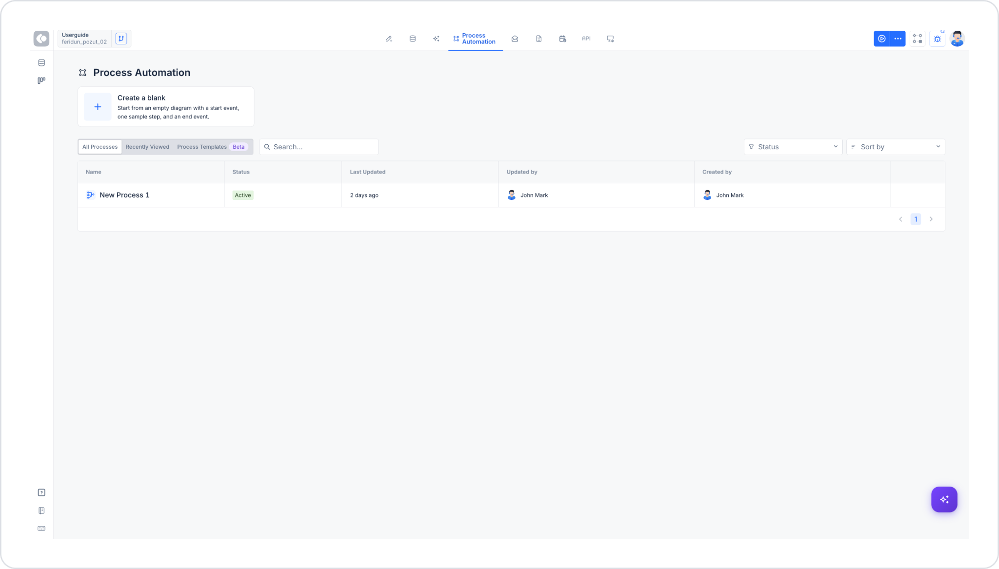
The Create a blank card at the top of the page is the starting point for creating a new process. When you click the “+” icon, the process begins with a blank diagram containing a start event, a sample step, and an end event.
Below the card is a table listing the existing processes in your project. This table can be accessed via three tabs:
In the upper-right corner of the list, there are two filtering/sorting options:
Additionally, a search box allows for quick searches by process name.
The table consists of the following columns:
Below the table, if the list spans multiple pages, there are forward and back arrow buttons to navigate between them.
If no processes have been created yet, the message “No processes yet — Create a blank process or start from a template.” appears in the table area.
When you create a process, the diagram screen consists of four tabs: Diagram, Parameters, Forms, Version History.
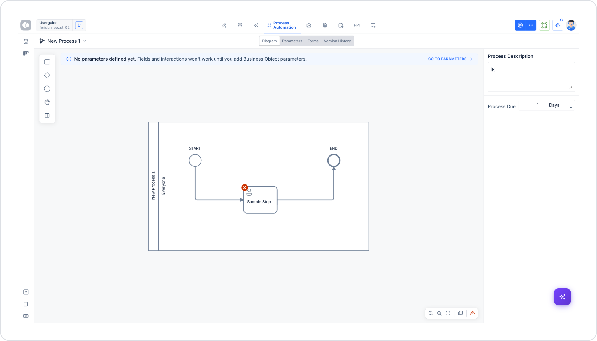
This is the main workspace (Canvas) where the process’s BPMN diagram is visually designed. The right panel displays general information about the process:
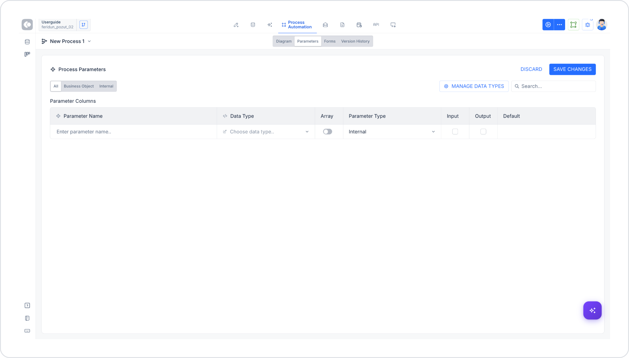
This is the tab where the process variables (parameters) are defined. The header reads Process Parameters; the DISCARD and SAVE CHANGES buttons are located in the upper right corner.
The parameter list can be viewed using three filters: All, Business Object, Internal. Custom data types can be managed using the MANAGE DATA TYPES button in the upper-right corner; parameters can be filtered using the search box.
The Parameter Columns list contains the following information for each parameter:
To add a new parameter, simply enter the parameter name in an empty row of the table; a new empty row is automatically added as the parameter is defined.
For example, you can define the “Permit Day” variable as the user’s leave day. If this data is information that must be entered by the user who initiates the process, parameters marked as Input appear under the Start Process action.
Internal-type parameters are used for logical checks. For example, in the leave approval process, you must create a process that checks whether the user is eligible for leave. Since this is a background operation, you can define a variable that determines permit eligibility—for example, a Boolean variable named “Progress Payment.”
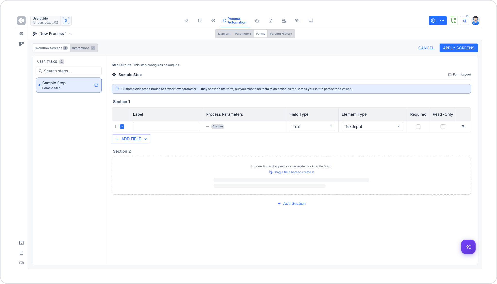
This tab is used to manage user screens (form fields) and user interactions (buttons) associated with the process. It consists of two sub-tabs: Workflow Screens and Interactions. For detailed information, see the “G. Forms Panel: Workflow Screens and Interactions” section below.
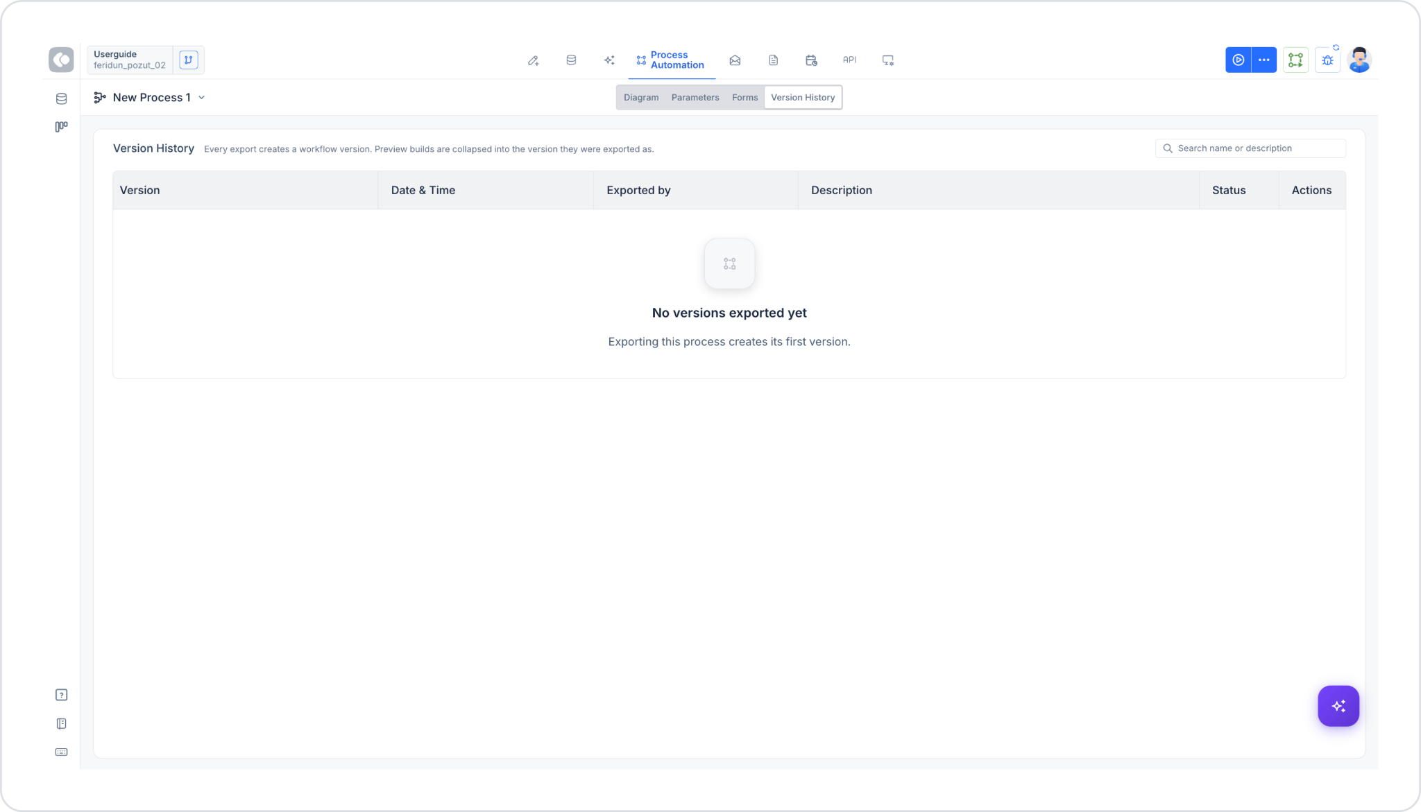
This tab lists the process’s past versions. Below the header, there is a note explaining the versioning logic: each export operation creates a workflow version; preview builds, however, are included within (collapsed into) the version they were exported from.
You can filter by version name or description using the search box in the upper right.
Each version record contains the following information:
If no versions have been exported yet, the message “No versions exported yet. Exporting this process creates its first version.” is displayed.
The toolbar on the left side of the diagram screen is organized into 5 groups. When you click on one of the icons, a panel opens showing the items belonging to that group:
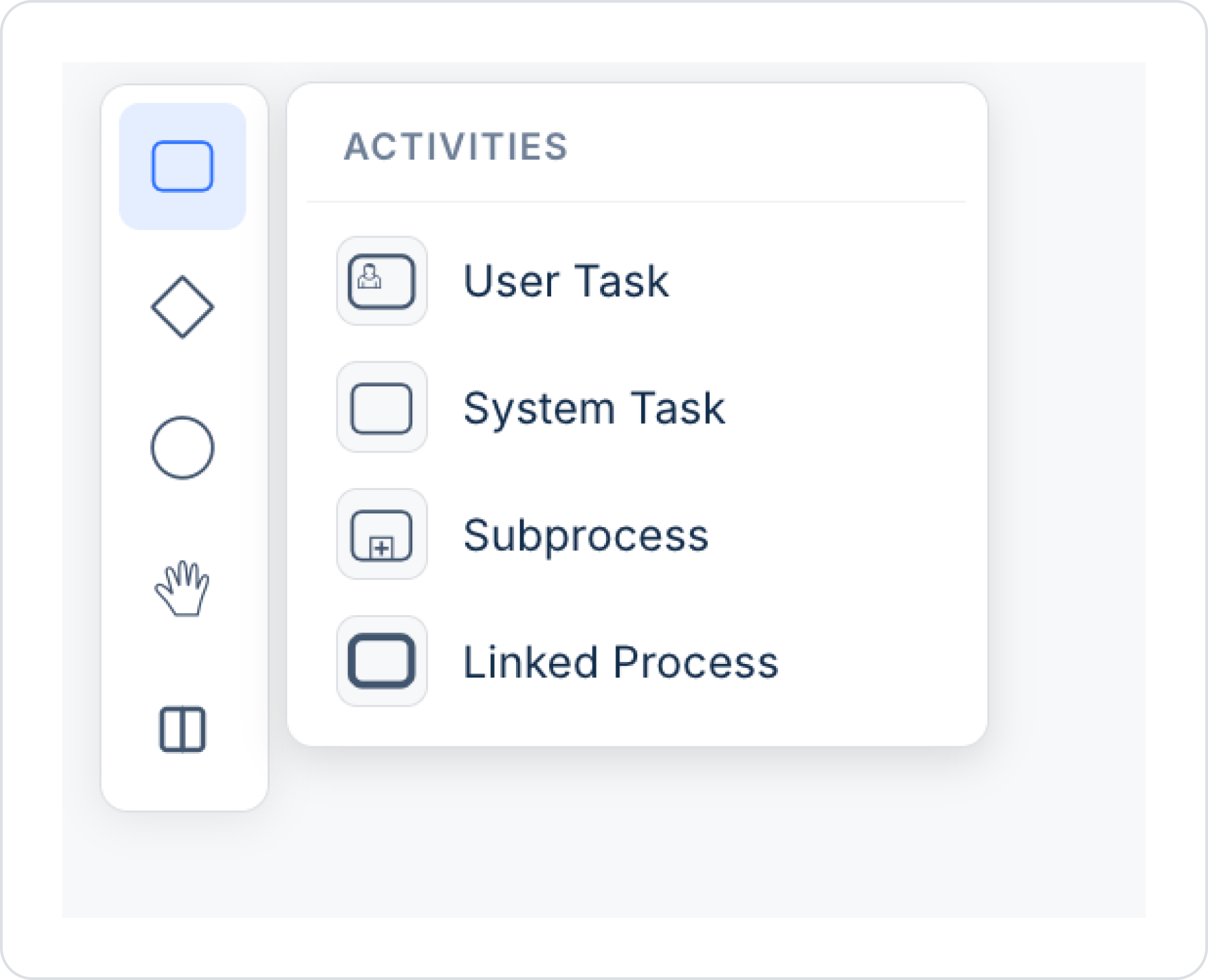
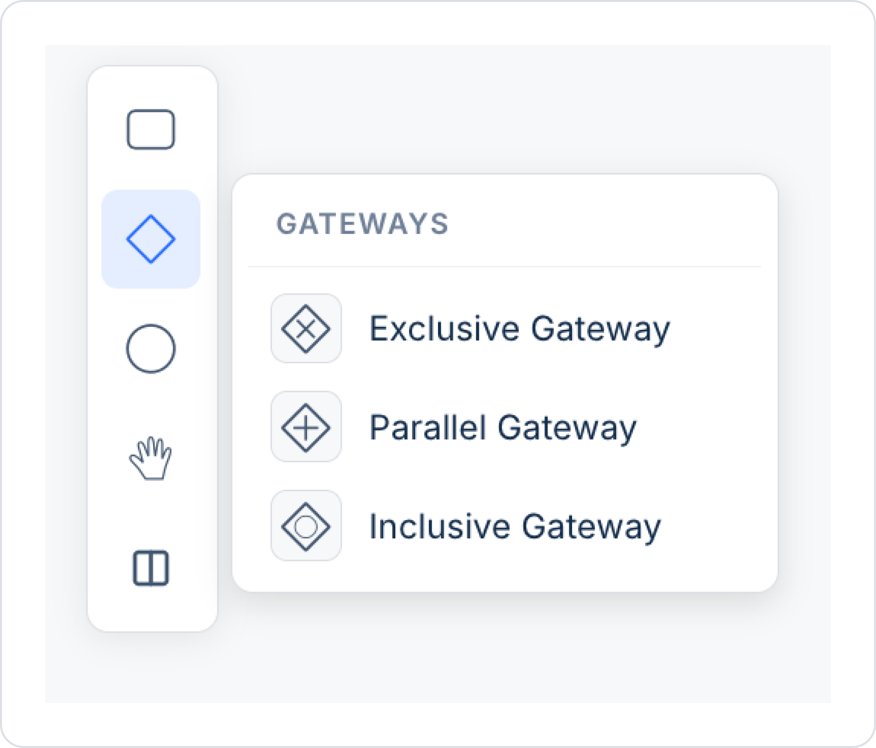
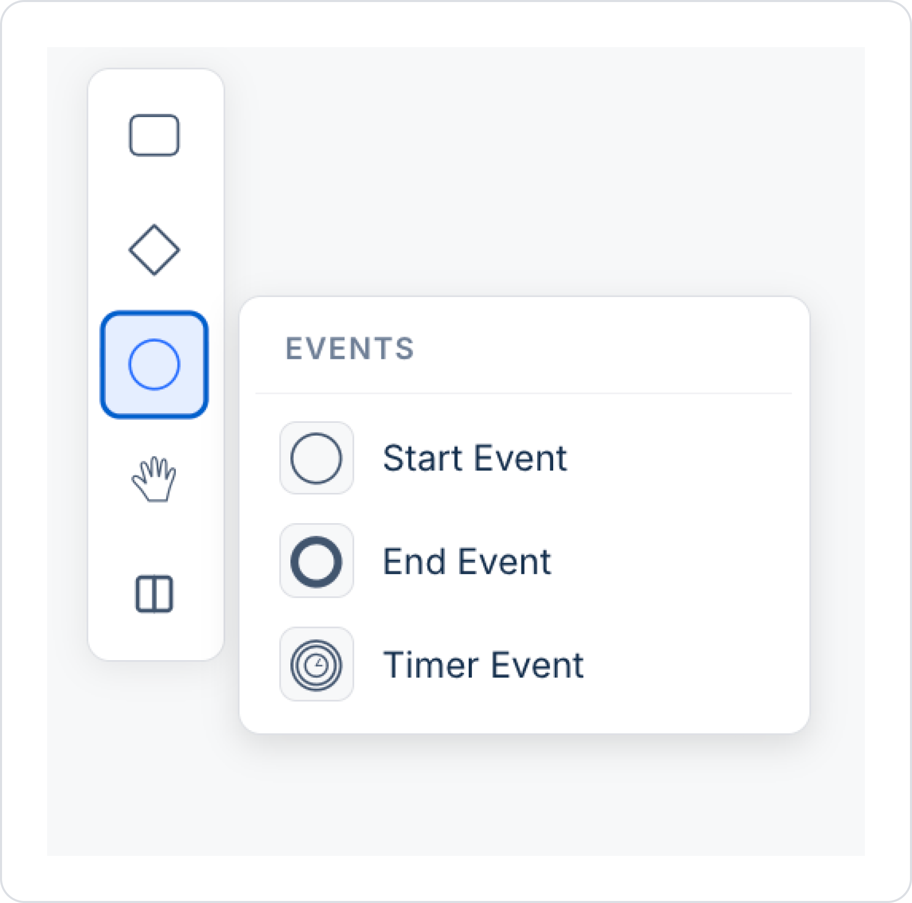
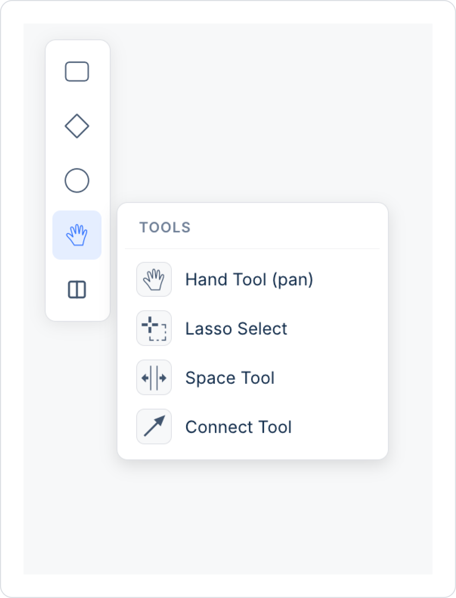
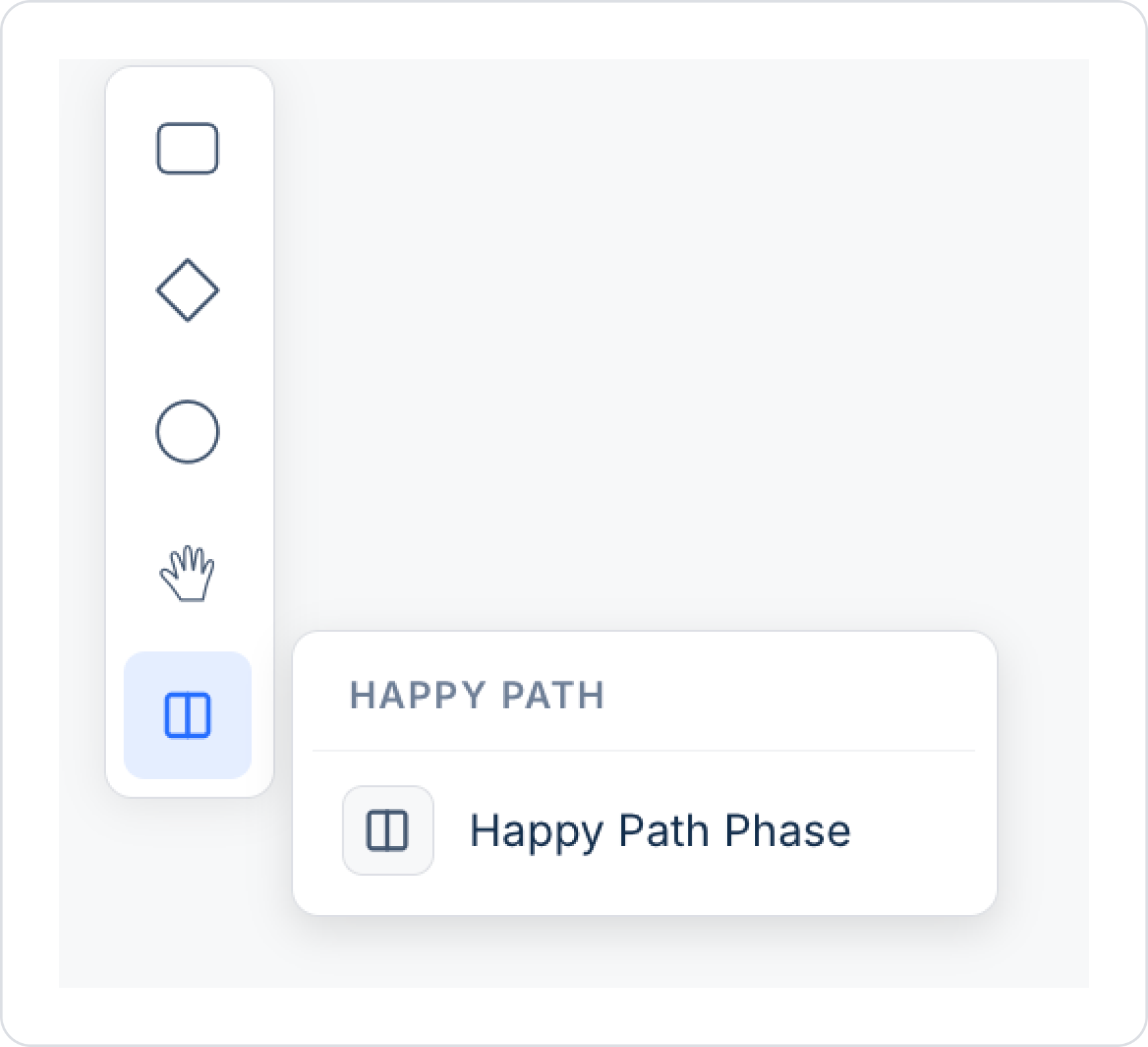
The Canvas is the main workspace where the workflow is visually created. Process steps, Gateways, and Events are placed on this area and connected to one another.
When you select an element on the canvas, a small tool menu (contextual toolbar) opens right next to the element. This menu consists of two rows and provides quick access to add, edit, or connect elements:
Top row — Addition tools:
Bottom row — Editing tools:
Workflow Designer instantly checks whether BPMN diagrams comply with both BPMN standards and Kuika platform rules. This validation mechanism ensures that incorrect or incomplete structures are detected early in the design phase.
The visibility of errors and warnings is controlled via the toggle located in the lower-left corner of the Process Automation screen.
For elements that violate rules:
When the cursor hovers over the icon, the violated rule is displayed as a tooltip.
Validated Rules:
This validation logic is applied in the same way during the preview and export stages.
Data related to processes executed in the Process Automation module—such as pending jobs, task history, process summary, and user load—can be queried through SQL Views. These Views allow for join operations with external queries; process data can be combined with other application data for use in reporting, analysis, and monitoring scenarios.
Example use cases:
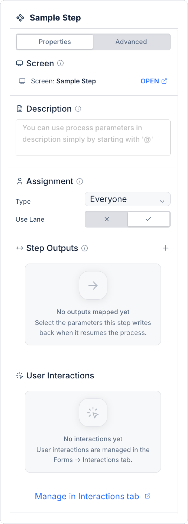
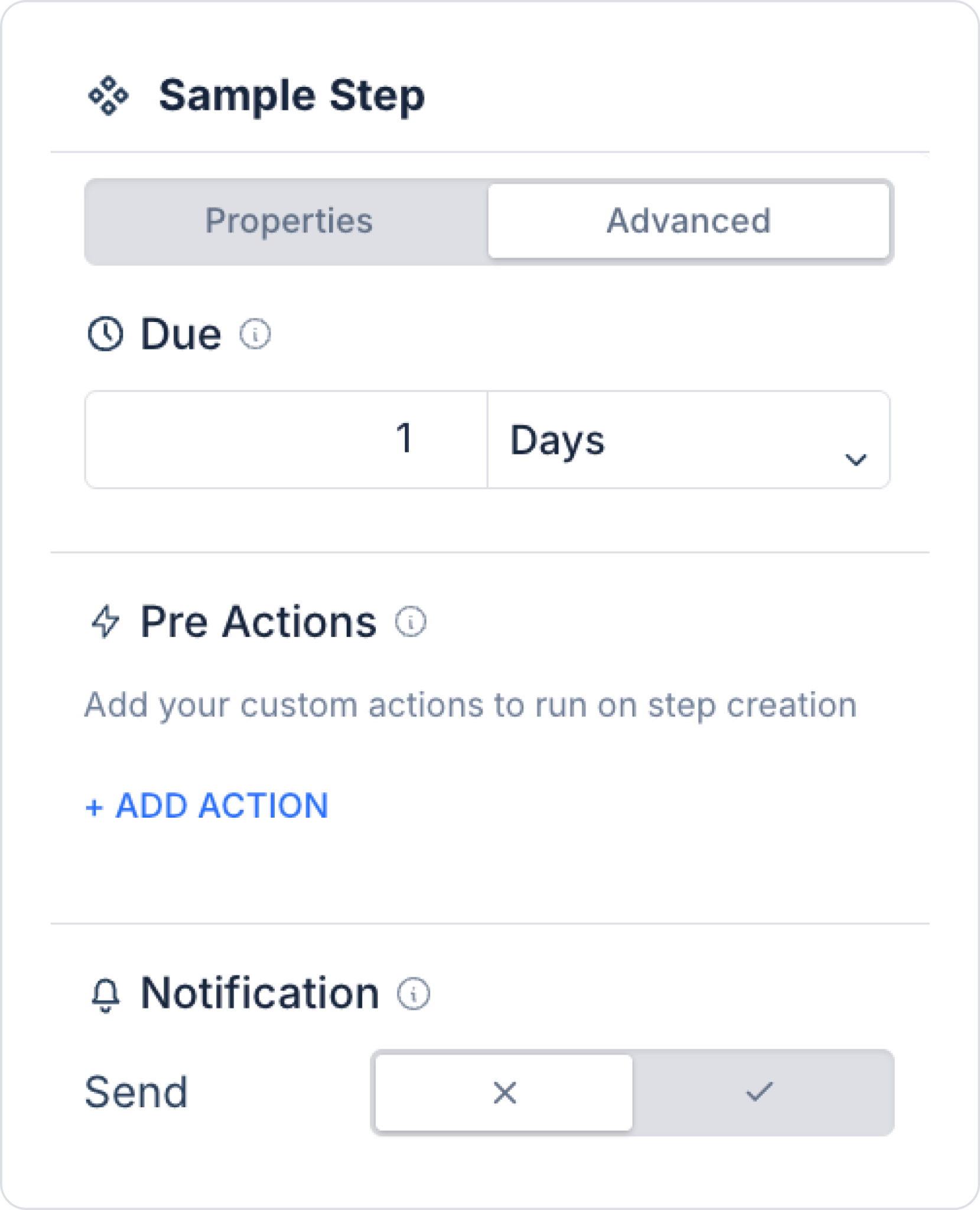
When you select a step (e.g., a User Task or System Task) on the canvas, a panel containing settings specific to that step opens in the right pane. This panel consists of two tabs: Properties and Advanced.
A Recurring Step is defined through a Timer Boundary Event attached to a specific Task or User Task. This structure allows the relevant step to be automatically rerun at defined time intervals or directs the process to an alternative flow after a specified time has elapsed.
Additionally, a Timer Event can be used as an independent step within the process. This usage is referred to as a Timer Intermediate Event. A Timer Intermediate Event causes the process to wait for a defined duration at the relevant point and allows it to proceed to the next step once the time has elapsed.
Use Cases:
Technical Specifications:
This tool allows you to define the conditions and order of operations in the workflow. The purpose of the Gateway is to ensure that, among multiple possible paths, only one is selected and executed based on defined conditions. This allows the process to branch according to different scenarios.
Variables defined in the parameter panel can be called using the Symbol Picker under the “None” option and used in conditions. These variables can be of different data types, such as string, number, boolean, or datetime. The parameter selected via the Symbol Picker is evaluated using a comparison operator specified in the Select Box (e.g., equals, not equals, greater than, less than, contains). If the condition is true, the output path associated with that condition is executed.
Multiple outputs can be defined on an Exclusive Gateway. One of these defined outputs must be designated as the default path using the “Will execute otherwise” option. This path is activated if none of the other conditions listed from top to bottom are met. If, for example, “Yes” is selected for this field, the first path checked in the workflow is evaluated as “No.” Order is important because the system evaluates conditions from top to bottom and does not check paths beyond the first condition that evaluates to true. Conditions can be reordered using drag-and-drop.
The order in which conditions are evaluated directly affects process behavior. The most general condition should be placed at the bottom, and the most specific condition at the top. Otherwise, an unexpected path may be executed if not all conditions are met. It is recommended to add a condition to every exit path. However, at least one path must be set to “Will execute otherwise” so that the path the process will follow when all conditions fail is clearly defined.
This tool is accessed from the Gateways group in the left-hand toolbar.
This is used to branch the workflow in parallel when multiple conditions can be met simultaneously. Unlike the Exclusive Gateway, the Inclusive Gateway ensures that all paths associated with these conditions are triggered simultaneously if more than one condition is true at the same time.
Independent conditions can be defined for each exit path. Conditions are created using variables in the parameter panel via the Symbol Picker. During evaluation, the system evaluates all conditions independently of one another. Therefore, if more than one condition returns “true,” all of these paths are executed simultaneously.
On the Inclusive Gateway, at least one path must be designated as “Will execute otherwise.” This option ensures that the process continues without interruption if none of the other defined conditions are met.
The Inclusive Gateway provides flexible parallel execution in workflow scenarios. For example, in an order process, if both the “Invoice Update” and “Return Request” conditions are met at the same time, the system can initiate both processes concurrently.
The Inclusive Gateway enables business processes to branch dynamically based on conditions and allows multiple operations to be initiated simultaneously.
This tool is accessed from the Gateways group in the left-hand tool panel.
It enables the parallel initiation of multiple tasks that must be executed simultaneously in a workflow or the merging of parallel paths. It is not condition-dependent; therefore, all exit paths are triggered simultaneously.
The Parallel Gateway is typically used for two purposes:
In the Split structure, all output paths connected to the gateway start simultaneously and execute independently of one another. In the Join structure, the Parallel Gateway waits for all parallel paths to complete and proceeds to the next step of the process only when this condition is met.
Using the Parallel Gateway enables time-optimized processes. For example, simultaneously initiating the “Packaging,” “Invoice Preparation,” and “Shipping Label Creation” steps after an order is approved speeds up the process.
Conditions are generally not defined for this tool in the Properties panel, as all paths are triggered automatically. However, the readability of the workflow can be improved by editing the names, descriptions, and connection directions.
This tool is accessed from the Gateways group in the left-hand tool panel.
This tool is the step where automatic tasks to be executed by the system on the Kuika platform are defined. It is typically used to model processes that do not require user interaction. For example, tasks such as making API calls, integrating with external services, updating system parameters, or preparing data in the background are performed in this step.
The System Task step contains two main components: Actions and Step Outputs. The Actions section is where the system actions to be triggered when this step runs are defined. Here, one or more previously defined actions can be executed sequentially. These actions can, for example, be a REST API call or send data to a previously defined Custom Action to receive a response.
Actions related to authorization can also be added from this section: Using the Add User To Role and Remove User From Role actions, you can automatically add or remove a user from a specific role when the step runs. For example, after an approval process is completed, the “Approved Users” role can be automatically assigned to the relevant user.
The Step Outputs section is where the data obtained as a result of the action is mapped to parameters that will be used in the workflow. In this section, the “+SELECT WF PARAMS TO MAP” option is used to determine which variables the values returned by the action will be assigned to. This ensures that values received from external systems or calculated in the background can be used later in the workflow for a condition, notification, or another task.
This task type does not display any forms or notifications to the user. It manages operations that take place entirely in the background. When placed appropriately, it automates the workflow and eliminates the need for manual intervention. Each System Task step can be configured not only to perform a single operation but also but also to execute a series of consecutive automated steps together.
This tool is accessed from the Activities group in the left-hand toolbar.
This tool is used to define tasks in the workflow that require manual data entry and approval from the user. It is used in situations where the user must perform a specific action, enter data, fill out a form, or make a decision. The process does not proceed to the next step until the user completes the assigned task. Therefore, User Task steps function as critical decision points or data collection points in the process.
User Task offers flexible configuration options for designing interactive processes with users in the system. This step can be linked to a form to collect data from the user and can be customized with various fields such as user-specific assignments, notifications, descriptions, due dates, and buttons.
This tool is accessed from the Activities group in the left-hand tool panel.
Properties Panel:
Example Buttons:
In Kuika’s Process Automation module, the Forms tab is used to manage business processes and to configure and visualize user-interactive steps. This tab ensures that the screens (forms) created for each business process are grouped under the relevant process and managed in an organized manner.
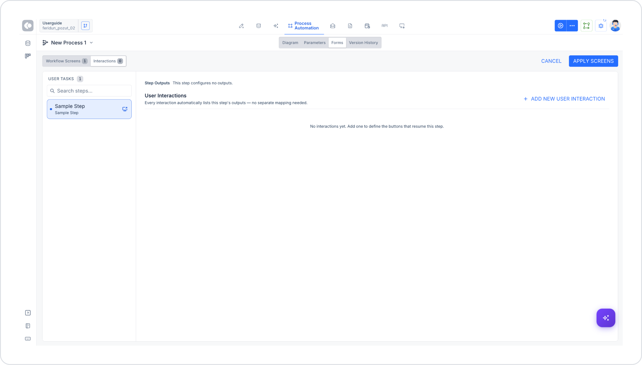
Each workflow has its own screen group. Thus:
The Forms tab consists of two sub-tabs: one titled Workflow Screens and the other Interactions. Next to each sub-tab is a counter indicating how many items are defined in that tab (e.g., “Workflow Screens 1,” “Interactions 0”). Changes are saved using the APPLY SCREENS button in the upper-right corner; they can be canceled using CANCEL.
In both sub-tabs, a list of all User Task steps in your process is displayed on the left under the USER TASKS heading. Steps can be filtered using the search box. When a step is selected from the list, the relevant content for that step (form fields or interactions) opens on the right.
In this sub-tab, the form fields (fields) are defined.
When a step (e.g., “Sample Step”) is selected from the USER TASKS list on the left, the following are displayed on the right:
Section Structure
A form is divided into one or more Sections. Each section is displayed as a separate block on the form. The following information is defined for each field added within a section:
To add a new field, click the + ADD FIELD button (select the field type from a drop-down menu).
To add a new section, use the + Add Section link at the bottom of the page. A section with no fields added yet is displayed as an empty drag-and-drop area with the message “This section will appear as a separate block on the form.” and the text “Drag a field here to create it.”
In this sub-tab, user interactions (buttons/User Interactions) associated with the selected step are managed.
When a step is selected from the USER TASKS list on the left, two sections open on the right:
To add a new interaction, use the + ADD NEW USER INTERACTION link in the upper right corner.
What Is a User Interaction?
The User Interaction element is used to define steps in a workflow that require human interaction, such as direct user feedback, form filling, decision-making, or the entry of specific data. This step separates the business process from system actions and requires user input.
Use Cases:
Technical Specifications:
Interaction Flow:
Tracking and Reporting:
Tips and Best Practices:
Advanced Usage: Form Integration
A form linked to a step in the “Workflow Screens” sub-tab supports the following features:
Multi-Instance settings are configured via the Multi-Instance Configuration panel under the Advanced tab when a step is selected. This structure applies to both Parallel Multi-Instance (PMI) and Sequential Multi-Instance (SMI).
Sequential Instance Count Strategy (SMI)
When the Sequential structure is selected, the instance generation method is specified in the Instance Generation field.
Manual (Number / Symbol): The number of instances is specified manually. In the subfield Instance Count (Fixed/Variable):
The specified number of instances is created and executed sequentially.
Based on Step Assignment: The number of instances is determined based on the step’s Assignment type. If the Assignment type is Role or Dynamic, instance generation follows this configuration.
Instance generation logic:
If Dynamic Assignment is used:
In a sequential structure, the processing order of instances can be specified:
Instances are created and executed sequentially according to the selected order.
Available in Sequential Multi-Instance steps. When the defined condition is met, any remaining instances that have not yet been executed are not created, and the process is terminated.
Conditions are defined using the AND GROUP structure.
The method for aggregating the results returned by child instances is specified in this section.
Child Output Key: Select the child output field to be included in the aggregation.
Strategy: Supported strategies:
Depending on the selected strategy, the child results are aggregated into a single output and transferred to the parent flow.
When the Parallel structure is selected:
In the Process Automation module, information about the user who initiates a process can be accessed via the Symbol Picker. This information is referred to as the Process Initiator and can be used as a dynamic value in various steps of the workflow (Task, User Task, Notification, Gateway conditions, etc.).
In the Symbol Picker, the following fields under Process Initiator can be selected individually:
This way, depending on the scenario, instead of displaying only the first and last name, functional data—such as the user’s email address—can be directly selected via the Symbol Picker and passed to actions.
Example Usage: In a leave request process, when the outcome of the request (approved/denied) needs to be communicated to the Process Initiator, an email can be sent directly to the user who initiated the process by selecting Process Initiator → Mail from the Symbol Picker in the “Recipients” field of the “Send Mail” action.
The Delegation System is a system that allows a user to delegate their tasks to another team member in their absence. For example, in an application that manages leave processes, if a manager is on leave, the delegation system kicks in so that an employee’s leave request can proceed without waiting for approval. The manager ensures that processes continue without interruption by appointing a delegate.
Thanks to the proxy system, the appointed proxy can view and manage the manager’s business processes on their behalf. This system makes processes more efficient and ensures business continuity. Within Process Automation, a user can assign a proxy to themselves to have their tasks managed by that proxy.
This system helps ensure that processes continue without interruption while facilitating the organized management of delegation assignments.
Kuika’s Process Automation module offers a powerful automation solution to accelerate business processes and increase efficiency. With this module, you can optimize your processes by minimizing manual tasks, thereby saving time and resources. You can use the Process Automation module to manage your processes more effectively and streamline your workflows.


