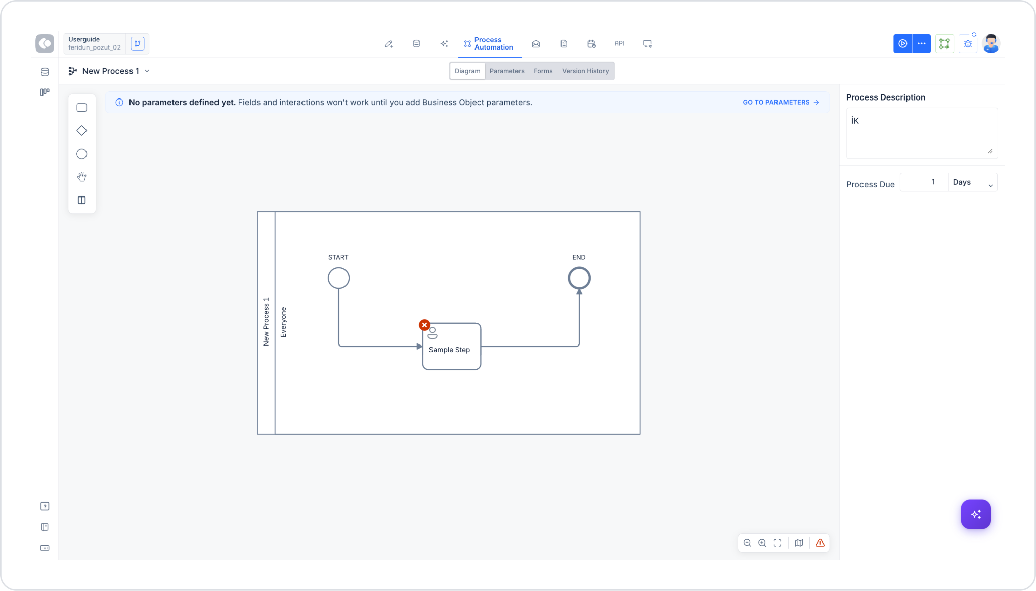
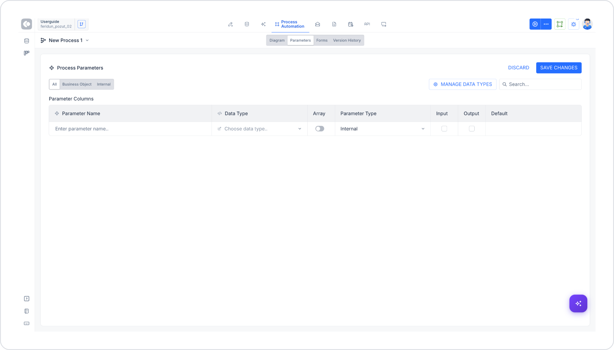
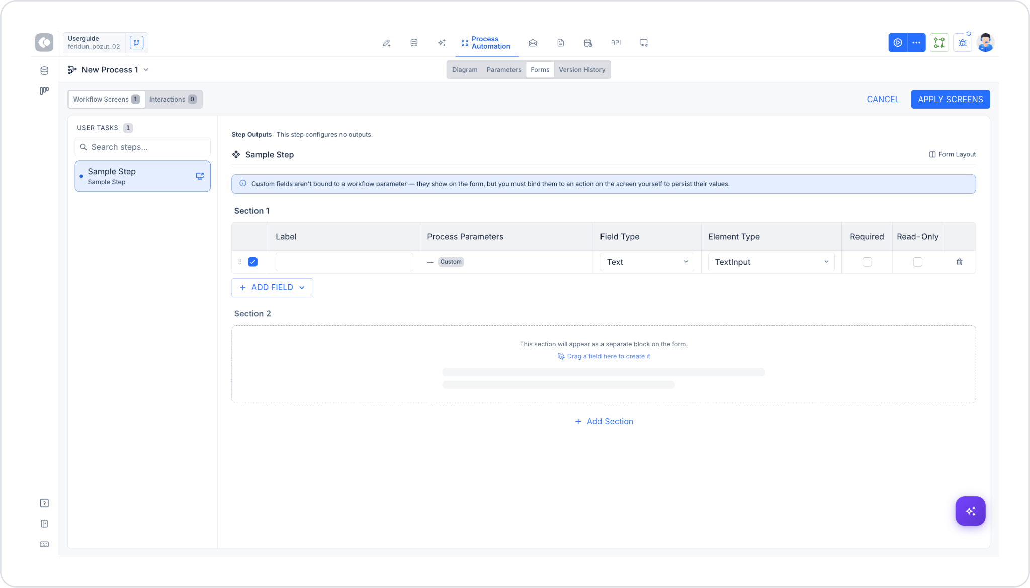
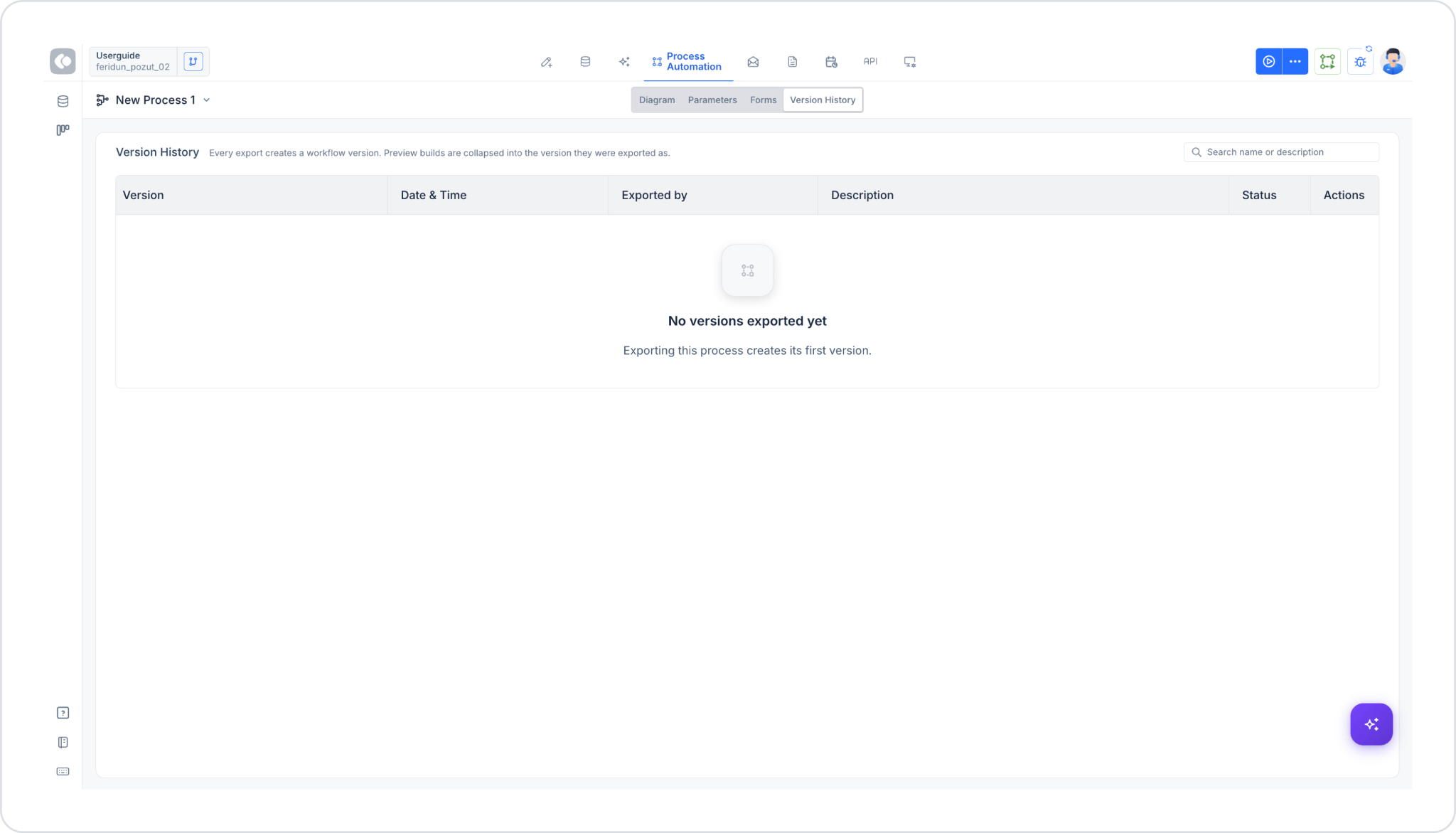
When you create a process, the diagram screen consists of four tabs: Diagram, Parameters, Forms, Version History.
Diagram Tab
This is the main workspace (Canvas) where the process’s BPMN diagram is visually designed. The right panel displays general information about the process:
Process Description: A text field explaining the purpose of the process.
Process Due: The field where you specify the timeframe (days, hours, etc.) by which the process must be completed.
Parameters Tab
This is the tab where the process variables (parameters) are defined. The header reads Process Parameters; the DISCARD and SAVE CHANGES buttons are located in the upper right corner.
The parameter list can be viewed using three filters: All, Business Object, Internal. Custom data types can be managed using the MANAGE DATA TYPES button in the upper-right corner; parameters can be filtered using the search box.
The Parameter Columns list contains the following information for each parameter:
Parameter Name: The name of the parameter (free-text entry).
Data Type: The parameter’s data type (selected from the “Choose data type…” drop-down list).
Array: A toggle option that determines whether the parameter is an array.
Parameter Type: The parameter’s type—it can be either Internal or Business Object.
Input: Indicates whether the parameter requires input from the user who initiates the process.
Output: Specifies whether the parameter’s value is returned as a result of the process.
Default: The parameter’s default value.
To add a new parameter, simply enter the parameter name in an empty row of the table; a new empty row is automatically added as the parameter is defined.
For example, you can define the “Permit Day” variable as the user’s leave day. If this data is information that must be entered by the user who initiates the process, parameters marked as Input appear under the Start Process action.
When a user initiates the workflow using the “Start Process” action, if the first task in the resulting process (in the WAITING state) belongs to that user, the user is directed directly to the relevant task screen without going through the task list.
Internal-type parameters are used for logical checks. For example, in the leave approval process, you must create a process that checks whether the user is eligible for leave. Since this is a background operation, you can define a variable that determines permit eligibility—for example, a Boolean variable named “Progress Payment.”
If the user is eligible for a permit day, the process proceeds along a specific path; if not, it proceeds along a different path.
Forms Tab
This tab is used to manage user screens (form fields) and user interactions (buttons) associated with the process. It consists of two sub-tabs: Workflow Screens and Interactions. For detailed information, see the “G. Forms Panel: Workflow Screens and Interactions” section below.
Version History Tab
This tab lists the process’s past versions. Below the header, there is a note explaining the versioning logic: each export operation creates a workflow version; preview builds, however, are included within (collapsed into) the version they were exported from.
You can filter by version name or description using the search box in the upper right.
Each version record contains the following information:
Version: Version number/name.
Date & Time: The date and time the version was created.
Exported by: The user who exported the version.
Description: A description of the version.
Status: The version’s status.
Actions: Actions available for the version (e.g., restore, view).
If no versions have been exported yet, the message “No versions exported yet. Exporting this process creates its first version.” is displayed.
The version history can be viewed in the mobile app, but versions are saved via the web.
C. Process Automation Tools
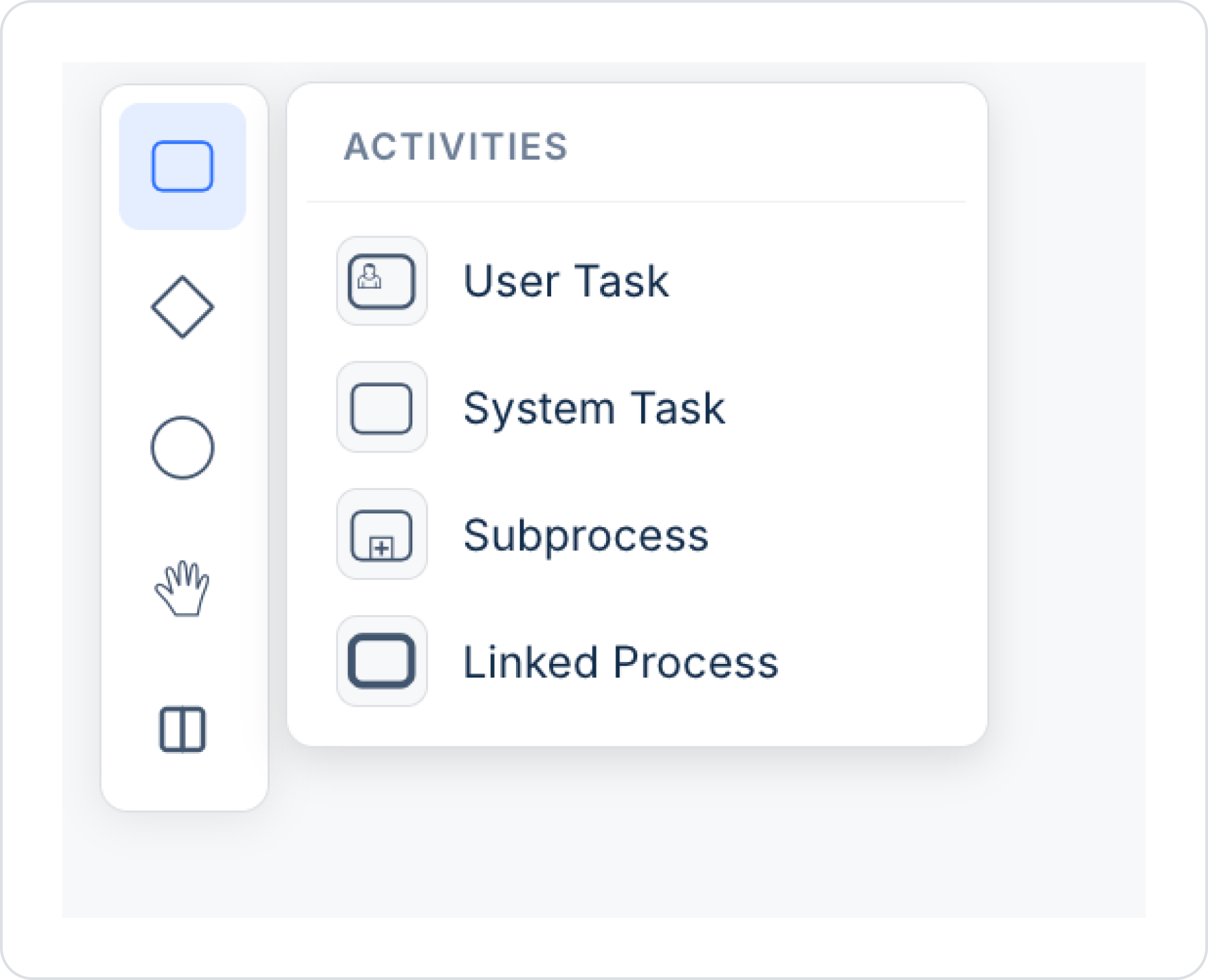
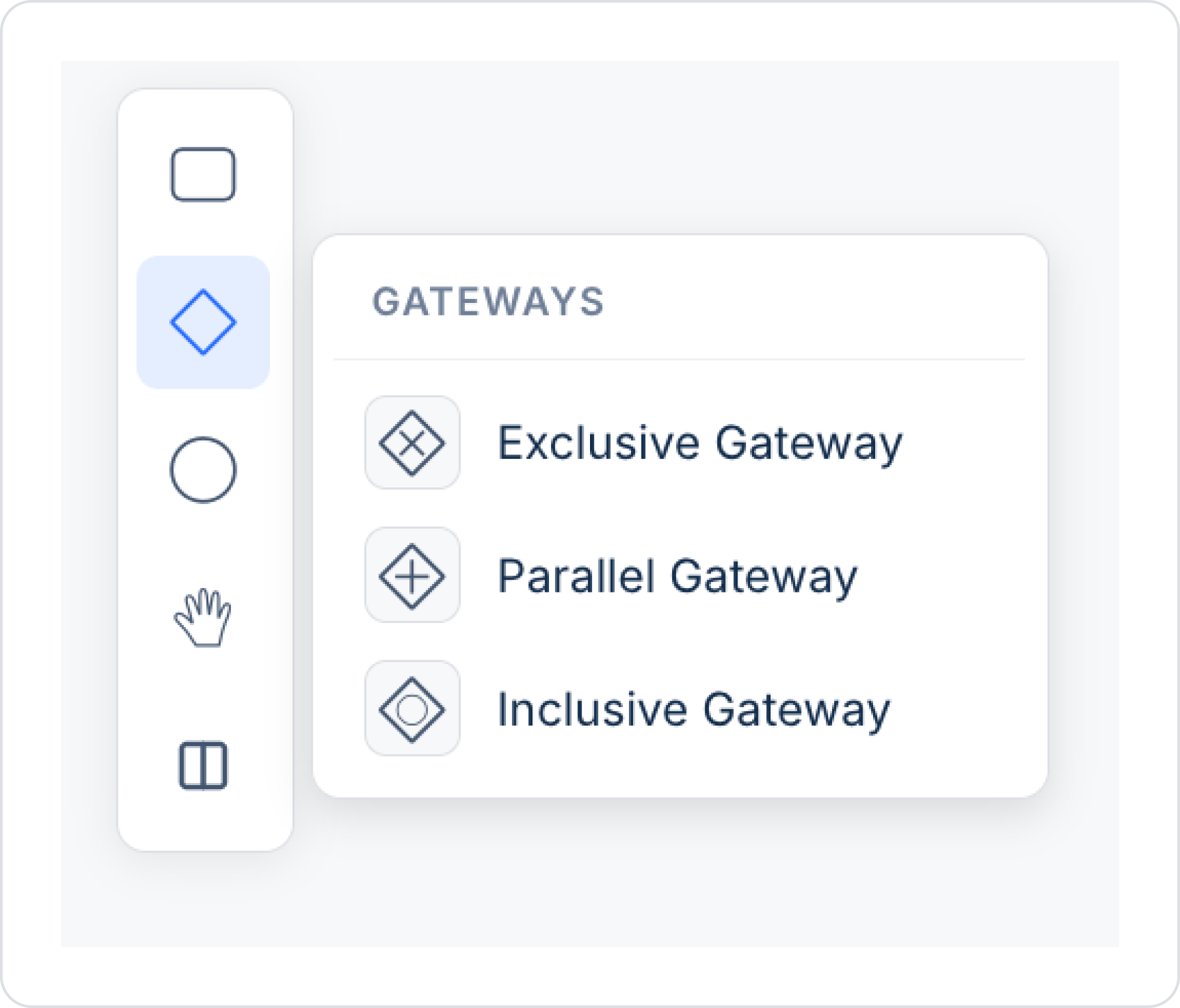
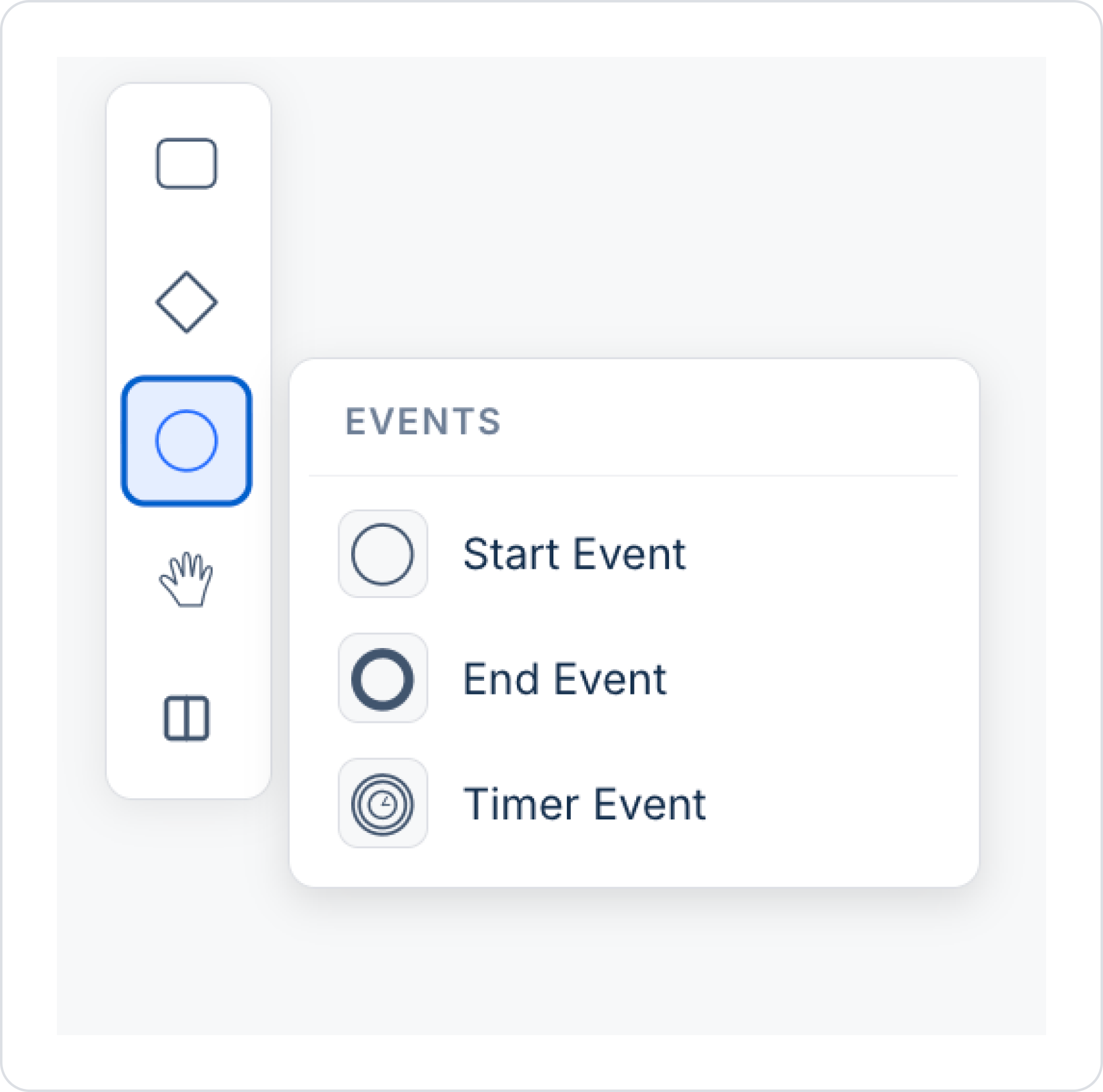
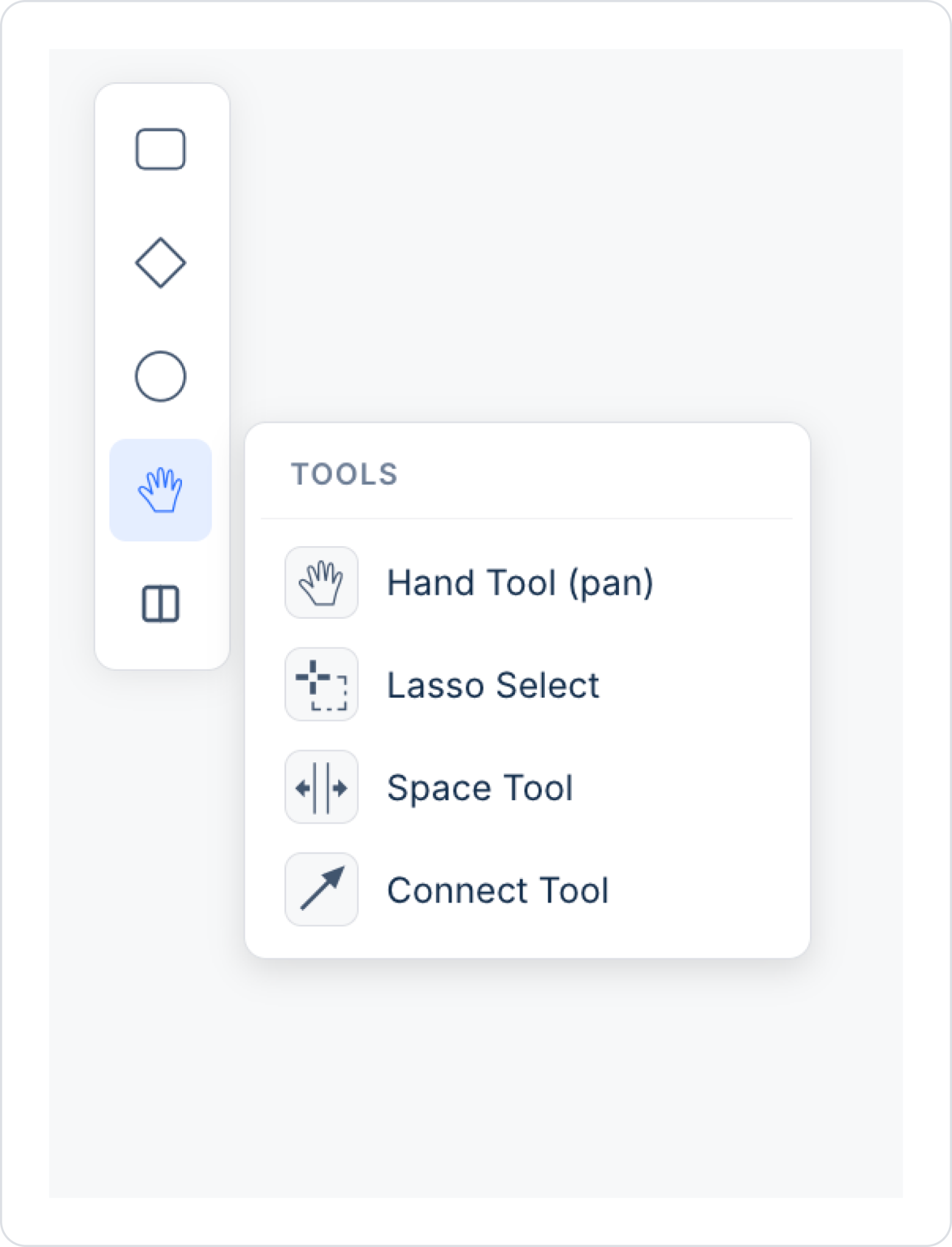
The toolbar on the left side of the diagram screen is organized into 5 groups. When you click on one of the icons, a panel opens showing the items belonging to that group:
Activities
User Task: These are tasks that require user interaction. User intervention is required for operations such as filling out forms or providing approval. Example: For “Manager Approval,” the relevant person is expected to fill out the form and provide approval.
System Task: These are tasks automatically executed by the system. Processes that do not require manual intervention—such as integration, data processing, or automated notifications—take place here. Example: After an order is approved, an invoice is automatically generated and emailed to the customer.
Subprocess: This organizes subprocesses under a single block, making the workflow more organized and readable. Detailed sub-steps are hidden within this block and can be opened and viewed only when necessary. Example: A separate subprocess is defined for the “Return Process”; it appears as a single block in the workflow, but when expanded, the detailed steps are listed.
Linked Process: Enables a direct connection between the current process and another process. This facilitates integration between different processes and allows for holistic management of the workflow. Example: A direct link is established from the “Order Management” process to the “Invoicing Process,” enabling transition between steps.
Gateways (Decision Points)
Exclusive Gateway: A decision point where, based on conditions, only one path is selected within the workflow. Conditions are defined using logical expressions. Example: If the order amount is greater than 1,000 TL, the process follows the “Manager Approval” path; otherwise, it follows the “Standard Process” path.
Parallel Gateway: Enables the start or merging of business processes that run in parallel. Tasks proceed concurrently and independently. Example: After “Order Approval,” the ‘Packaging’ and “Invoice Preparation” tasks begin simultaneously.
Inclusive Gateway: A decision point where one or more paths can be selected simultaneously based on specific conditions. The difference from an Exclusive Gateway is that more than one condition can be met at the same time. Example: If both the “Return Request” and “Invoice Update” options are checked on an order, both steps are executed simultaneously.
Events
Start Event: Represents the starting point of the workflow. It is the first step that triggers the process and can be a user action, a system event, or a timer. There should generally be only one starting point for the workflow to function correctly. Example: The “Customer Order Received” event starts the workflow.
End Event: Indicates the point where the workflow is completed and ends. The process ends, and results are recorded or notifications are sent as needed. Example: The “Order Completed” step ends the workflow.
Timer Event: A timer that triggers the workflow at the end of a specified duration or at specific times. It is used as a wait step. The wait duration can be set using the Time Duration parameter. The “Is Interrupting” option controls whether the process is paused during the wait. Example: The “Wait for Payment” step waits for 3 days; at the end of this period, the “Send Payment Reminder” step is automatically triggered.
Tools
Hand Tool (pan): Allows you to drag and move the workflow on the design screen. It is used to quickly focus on or edit different sections in complex workflows. It provides mobility during design and enhances the user experience. Example: In a large order management process, you drag the workflow to the right to make the “Order Approval” step more visible.
Lasso Select: Allows you to select multiple workflow elements at once and perform bulk operations such as moving, copying, or deleting them. It saves time and offers convenience in complex processes. Example: You want to select the “Invoice Preparation,” “Payment Approval,” and “Shipping Preparation” steps and move them all to the left at once.
Space Tool: Allows you to add or remove space between objects in the workflow. It creates space to add new steps or saves space by removing unnecessary gaps. Example: You create space between “Customer Approval” and “Order Shipping” to add a new “Quality Control” step.
Connect Tool: Used to link different elements in the workflow. It creates connections that indicate the direction of data or control flow. Example: You direct the workflow by drawing an arrow from the “Order Received” step to the “Inventory Check” step.
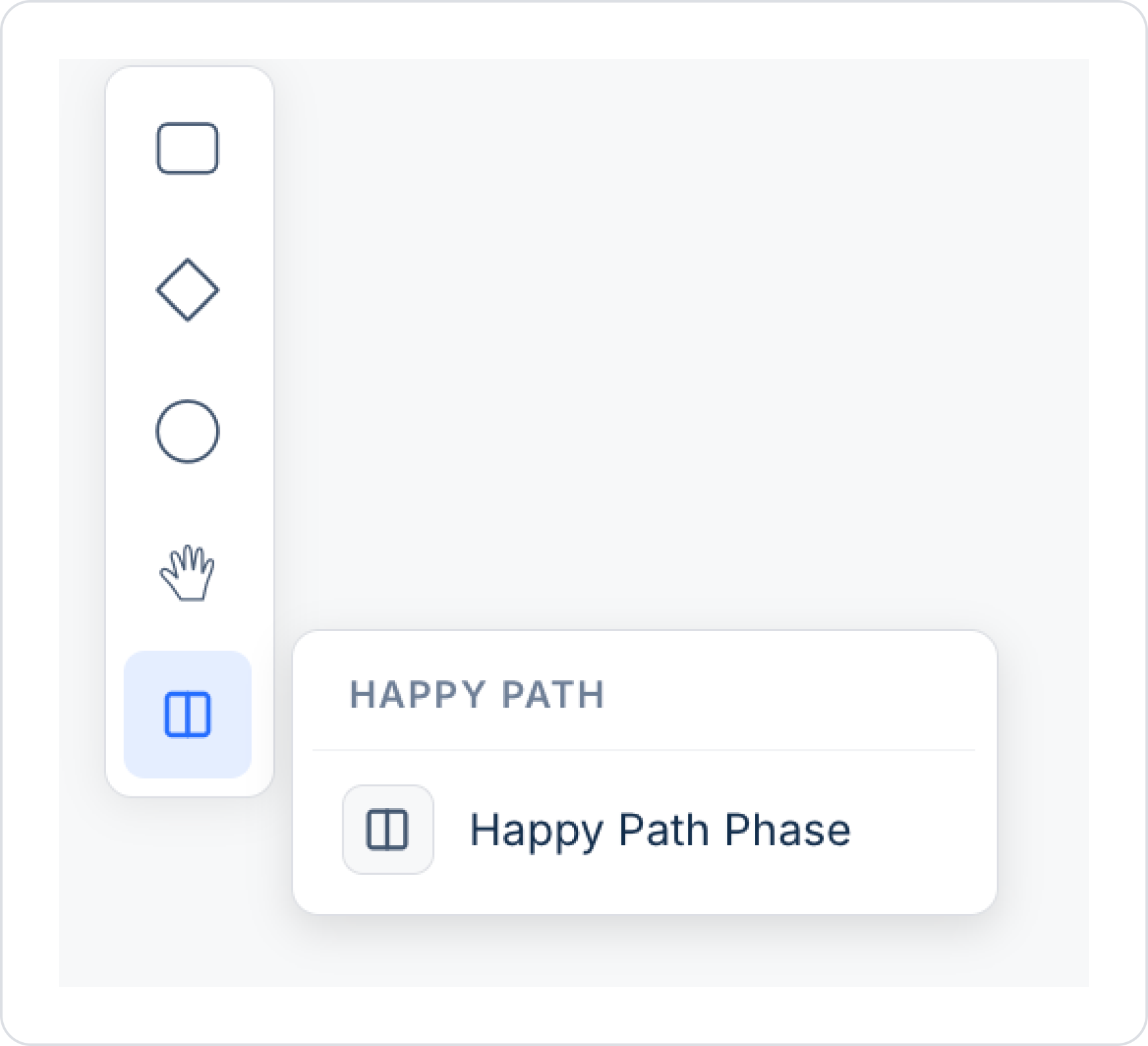
Happy Path
Happy Path Phase: Allows you to visually group the main/expected flow of the process (happy path) as a separate phase or lane on the canvas. This makes the main flow, which is distinct from exception or alternative scenarios, more readable.
D. Workflow Designer and Design Area (Canvas)
The Canvas is the main workspace where the workflow is visually created. Process steps, Gateways, and Events are placed on this area and connected to one another.
Selecting Elements on the Canvas (Contextual Toolbar)
When you select an element on the canvas, a small tool menu (contextual toolbar) opens right next to the element. This menu consists of two rows and provides quick access to add, edit, or connect elements:
Top row — Addition tools:
Appended End Event (circle icon): Allows you to add an End Event directly to a selected element. This feature lets you quickly conclude the workflow. Example: By selecting this icon from the menu that appears when you click an “Order Cancellation” step, you can ensure that the cancellation ends the workflow.
Append Text Annotation (slash/note icon): Allows you to add a description box to the selected item. Descriptions make the workflow logic easier to understand and facilitate communication within the team. Example: By adding the note “Product is visually inspected” to the “Quality Control” step, you can provide information about the purpose of this step.
Create Task (rectangle icon): Allows you to add a task to the selected item. This task can be a process that the system executes automatically. Example: By adding a “Transfer to CRM” step after the “Customer Registration” step, you can ensure that the data is automatically recorded in the system.
Create Exclusive Gateway (equilateral triangle icon): Allows you to add a decision point (Exclusive Gateway) after the selected element. This step changes the direction of the workflow based on specific conditions. Example: After the “Payment Status” check, you can add a “Is Payment Complete?” decision step to create different paths.
Bottom row — Editing tools:
Change Type (key/wrench icon): Allows you to change the type of the selected element. This enables you to convert an element selected by mistake during the design process without having to recreate it. Example: If you accidentally added a “Task” element as a standard task, you can convert it to a “User Task” to turn it into a step requiring user interaction.
Remove (trash can icon): Allows you to delete the selected element(s). Used to quickly remove incorrect or unnecessary steps. Example: You can select the “Manual Check” step that is no longer functional and delete it using this icon.
Connect Using Sequence Flow / Message Flow / Association (arrow icon): Used to establish connections between elements.
Sequence Flow: Represents the process flow.
Message Flow: Facilitates message communication between different pools or lanes.
Association: Establishes relationships between elements using information annotations; for example, it is used to link forms and descriptions. Example: You can define the workflow by drawing a Sequence Flow between the “Create Invoice” step and the “Send Invoice” step. You can also add a description using a Text Annotation and link it to the “Create Invoice” step via an Association.
Workflow Designer Validation (Rule Checks)
Workflow Designer instantly checks whether BPMN diagrams comply with both BPMN standards and Kuika platform rules. This validation mechanism ensures that incorrect or incomplete structures are detected early in the design phase.
The visibility of errors and warnings is controlled via the toggle located in the lower-left corner of the Process Automation screen.
For elements that violate rules:
If there is only a warning, the warning (exclamation mark) icon is displayed;
If there is an error, or if both an error and a warning are present, the error (x) icon is displayed.
When the cursor hovers over the icon, the violated rule is displayed as a tooltip.
Validated Rules:
Requirement for a default path and condition in Exclusive Gateways
Parallel and Inclusive Gateway branches must merge into a join Gateway of the same type
Gateways must not be used as “split” gateways with a single output
Task and User Task steps must not be empty or have a label consisting solely of whitespace
Each node must have at least one incoming or outgoing connection
A screen must be assigned to each User Task
The diagram must contain at least one Start Event and one End Event
This validation logic is applied in the same way during the preview and export stages.
Accessing Process Data via SQL
Data related to processes executed in the Process Automation module—such as pending jobs, task history, process summary, and user load—can be queried through SQL Views. These Views allow for join operations with external queries; process data can be combined with other application data for use in reporting, analysis, and monitoring scenarios.
Example use cases:
Reporting the number of pending tasks per user by combining it with data from other tables
Exporting task history to external systems or summary screens
Analyzing user load by department or role
E. Process Automation Properties Panel
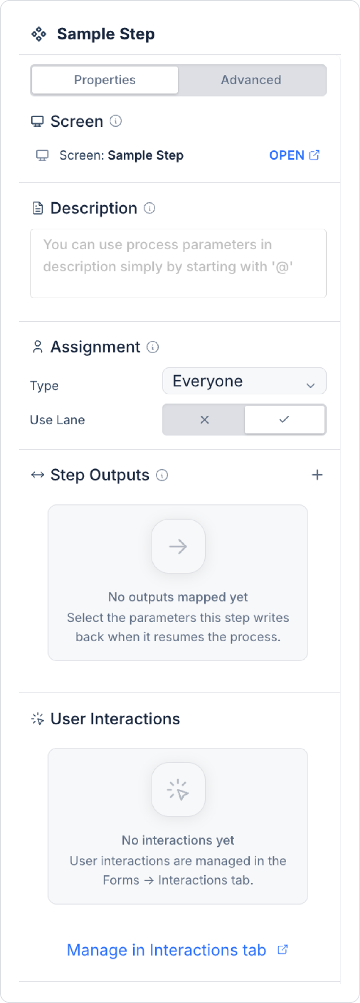
When you select a step (e.g., a User Task or System Task) on the canvas, a panel containing settings specific to that step opens in the right pane. This panel consists of two tabs: Properties and Advanced.
Properties Tab
Screen: Displays the screen associated with the step. You can open the relevant screen directly by clicking the “OPEN” link.
Description: The field where the step’s description is entered. Within the description, you can directly reference process parameters by starting with the @ symbol.
Assignment: This is where task assignments are made.
Type: Determines who the task is assigned to (Everyone, Role, Dynamic Assignment, External Users — see Type Options below).
Use Lane: A toggle that determines whether the assignment will use the lane structure in the diagram.
Step Outputs: This is where the parameters that the step will write back as the process continues are mapped. A new output can be added using the “+” icon; if no mapping has been done yet, the message “No outputs mapped yet” is displayed.
User Interactions: This is where the user interactions associated with the step are listed. These interactions are managed not directly from this panel, but from the Forms → Interactions tab. If no interactions have been defined yet, the message “No interactions yet” is displayed, and you can navigate to the relevant tab via the “Manage in Interactions tab” link.
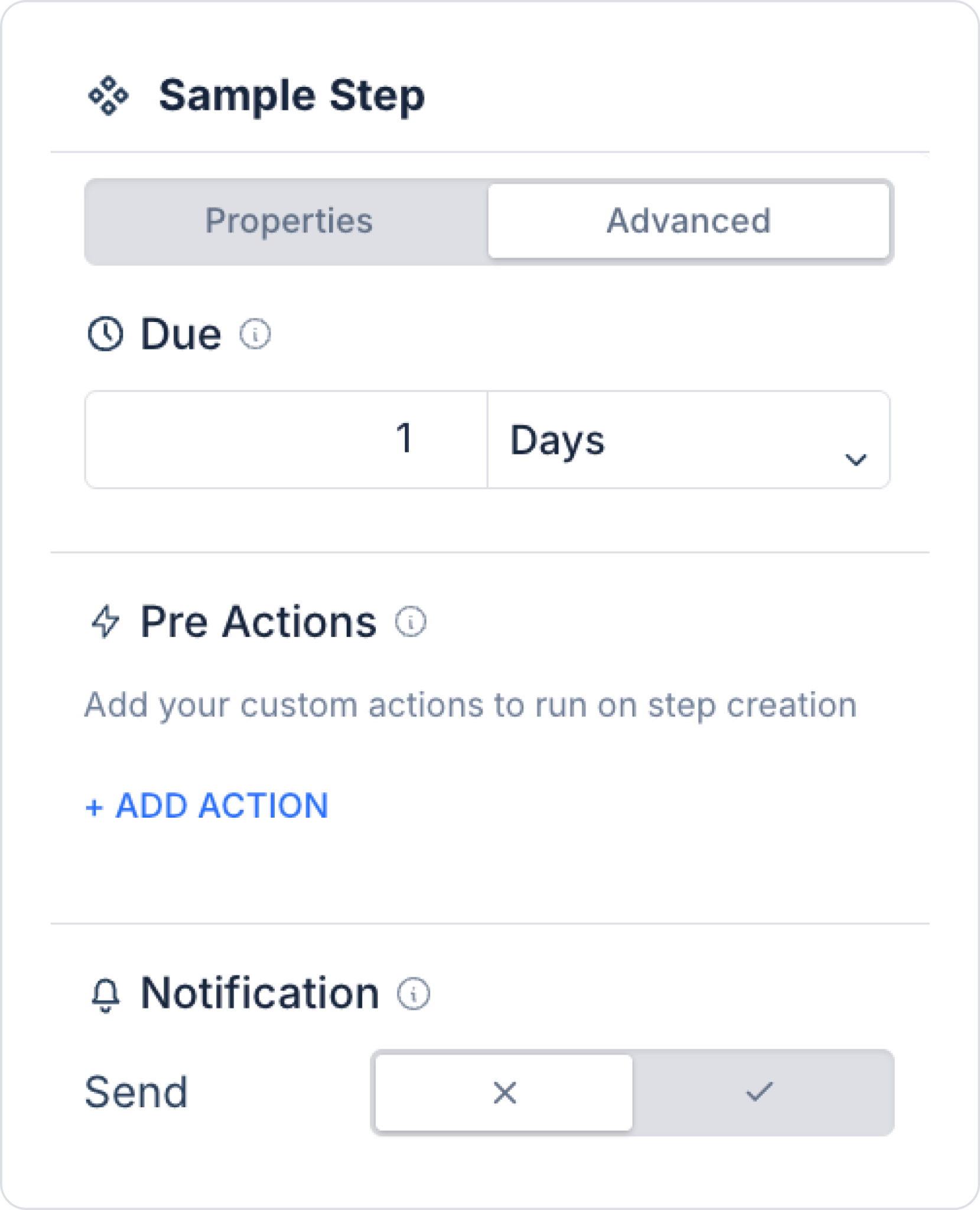
Advanced Tab
Due: The timeframe by which the step must be completed (e.g., 1 Days). Units such as days, hours, etc., can be selected.
Pre Actions: This is the area where custom actions to be automatically executed when the step is created (step creation) are defined. A new action can be added using “+ ADD ACTION.”
Notification: This is the area where you configure whether a notification related to the step should be sent (Send: on/off).
Type Options
Everyone: When this option is selected, the task is added to the task pool. All users can view this task; any user who wishes to can claim the task and complete it.
Role: The task is assigned to a specific role defined in the system. To assign a role, select the appropriate role from the “Choose Role” field. Available roles are displayed in the role list, and a new role can be created using the “+ Add New Role” option.
Dynamic Assignment: Allows for assignments linked to process variables.
External Users: Enables external users outside the application to be assigned to tasks. This is used, for example, when customers, subcontractors, or guest users need to complete a step.
Recurring Step (Scheduled Steps)
A Recurring Step is defined through a Timer Boundary Event attached to a specific Task or User Task. This structure allows the relevant step to be automatically rerun at defined time intervals or directs the process to an alternative flow after a specified time has elapsed.
Additionally, a Timer Event can be used as an independent step within the process. This usage is referred to as a Timer Intermediate Event. A Timer Intermediate Event causes the process to wait for a defined duration at the relevant point and allows it to proceed to the next step once the time has elapsed.
Use Cases:
Sending a reminder email or notification when a task is not completed within a specific timeframe
Triggering tasks that run periodically (e.g., daily reports, weekly checks)
Continuing the process via an alternative path in steps delayed by the user
Technical Specifications:
It is linked to the task item by selecting the “Timer Boundary Event.”
The wait time (minutes, hours, days) is specified in the “Timer Duration” field.
If the “Is Interrupting” option is enabled, the main flow is paused when the time elapses, and the timer path is executed.
If disabled (non-interrupting), the timer path runs in parallel while the main flow continues.